

CVSiR Cell Voltage Simulator
Make testing safer, simplerand more repeatable.
High-Cell-Count Validation
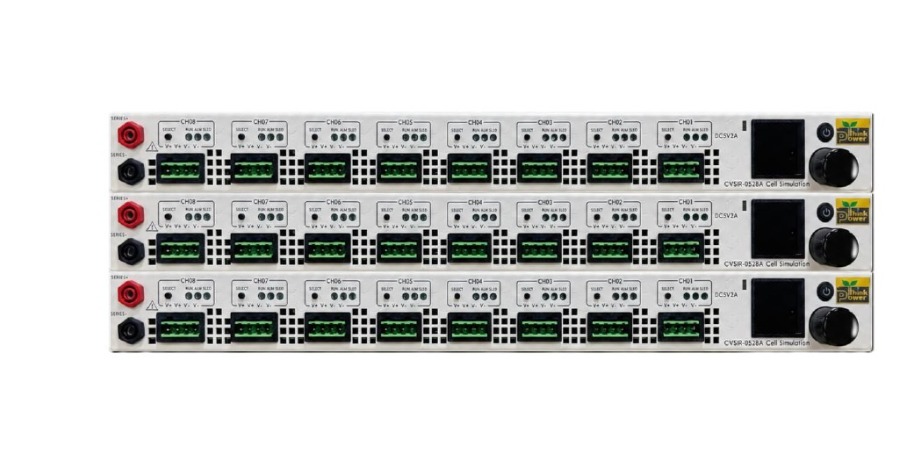
CVSiR-0524A / 4CH, scalable up to 20 cells
CVSiR-0528A / 8CH, scalable up to 160 cells
160CH Synchronized Output < 10 ms
Up to 160CH synchronized output
For multi-unit testing
Dual-Range Current Measurement
0 ~ 2200 mA ±0.5 mA, 0.1 mA resolution
0 ~ 3300 μA ±1 μA, 0.1 μA resolution
AI Agent Ready
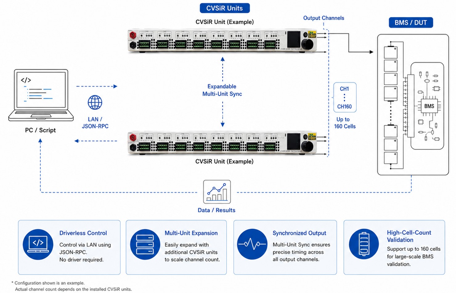
JSON-RPC, JSON Schema, and OpenRPC enable
driverless integration for scripts, ATE, and AI agents
System Connection Overview
From CVSiR Channels to High-Cell-Count BMS Validation
BMS Validation Scenarios
From Cell Simulation to Real Test Cases
CVSiR helps engineers reproduce key BMS validation conditions without relying on real battery cells.From voltage accuracy checks to abnormal-cell behavior and synchronized multi-channel output,each channel can be configured, measured, and repeated with consistent test conditions.
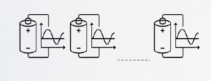
Cell Voltage Simulation
Simulate individual cell voltages from normal operatingconditions to boundary conditions for BMS voltage sensingvalidation.
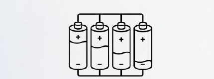
Cell Imbalance Test
Create controlled voltage differences between cells toverify imbalance detection, warning logic, and protectionbehavior.

Overvoltage / Undervoltage Protection
Reproduce OVP and UVP trigger and release conditionswith repeatable voltage steps for protection thresholdverification.

Cell Balancing Verification
Measure balancing behavior and current response toconfirm BMS passive balancing operation and controltiming.

Open / Short / Abnormal Cell Simulation
Create controlled abnormal-cell conditions, includingopen-cell, short-cell, and fault-state scenarios, to verifyBMS detection and protection behavior.
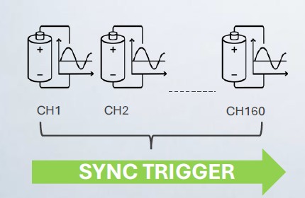
Synchronized Multi-Channel Output
Preload voltage settings and trigger synchronized outputacross multiple channels and units, enabling consistenthigh-cell-count BMS validation.
Synchronized Multi-Channel Output < 10 ms
API & Automation Integration
Driverless control for modern BMS validation systems
JSON-RPC 2.0
Cross-platform, driverless controlNo legacy DLLs required
JSON Schema
Built-in parameter validationbefore hardware execution
OpenRPC
Machine-readable APIspecification for scripts, AI agents,and automated test systems
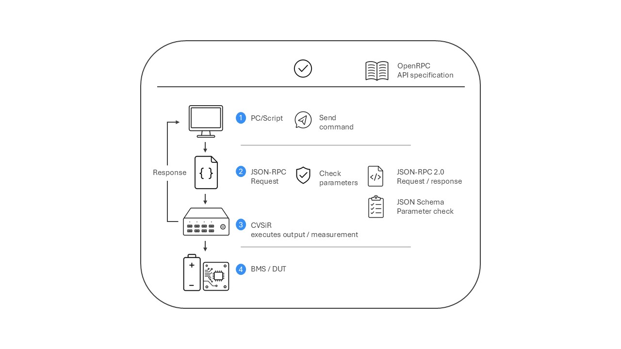
Built for Open Automation
CVSiRis designed for script-based and automated BMS validation.
Through JSON-RPC, test systems can control the device directly without legacyDLLs or platform-dependent drivers.
JSON Schema validates parameters before hardware execution, while OpenRPC providesmachine-readable API specifications for faster integration with software, ATE, and AI agents.
JSON-RPC 2.0Cross-platform, driverless controlNo legacy DLLs requiredJSON SchemaBuilt-in parameter validationbefore hardware executionOpenRPCMachine-readable APIspecification for scripts, AI agents,and automated test systems
Specifications
Scalable 4CH / 8CH architecture for high-cell-count BMS validation
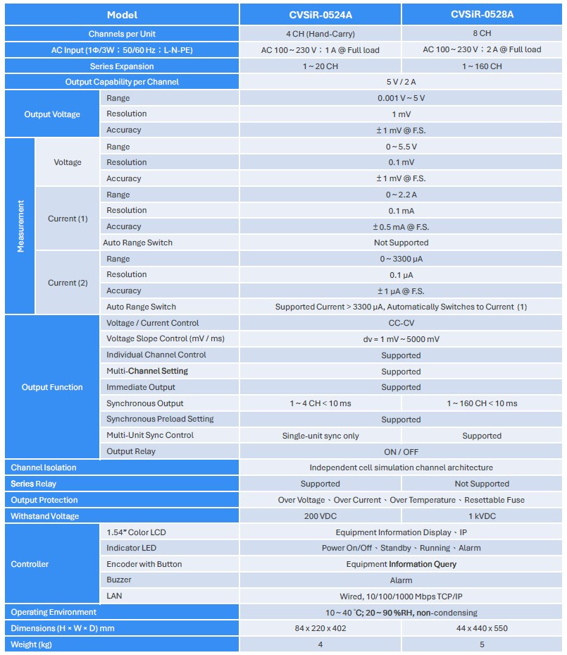
Functional Description
Channel output, measurement, synchronization, and protection overview
CVSiR integrates programmable cell-voltage simulation output, voltage / current measurement, multi-channel synchronized output, protection functions, and local interface control into a single-unit 4CH / 8CH architecture or an expandable 1~160 CH system.
The following functional description summarizes the key functional blocks used for BMS validation and system integration.
Cell Voltage Output
Provides programmable cell voltage output for BMS cell input simulation. Each channel can be configured independently.
Voltage Range Control
Supports output voltage setting from 0.001 V to 5 V for normal cell voltage and boundary-condition testing.
Voltage Measurement
Monitors channel voltage up to 5.5 V with high-resolution measurement for voltage sensing validation.
Dual-Range Current Measurement
Measures both load-level current and micro-current through two measurement ranges.
Range 1:
0 ~ 2.2 A range for balancing current, load response, and higher-current validation conditions.Auto range switching is not supported for Range 1.
Range 2:
0 ~ 3300 μA range for cell-pin current, leakage current, and low-current observation.Auto range switching is supported for Range 2.
Output Relay
Provides output ON / OFF control for channel connection, isolation, and test-state switching.
CC-CV Control
Supports constant-voltage output with current-limit control. Users can set the output voltage for cell simulation and controlled test operation.
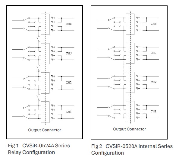
Series Relay Configuration
This function is available only on the CVSiR-0524A model.
The output can be configured as four fully independent channels, CH1–CH2 series and CH3–CH4 series, CH1–CH2–CH3 series, or CH1–CH2–CH3–CH4 series.Refer to Fig. 1 and Fig. 2.
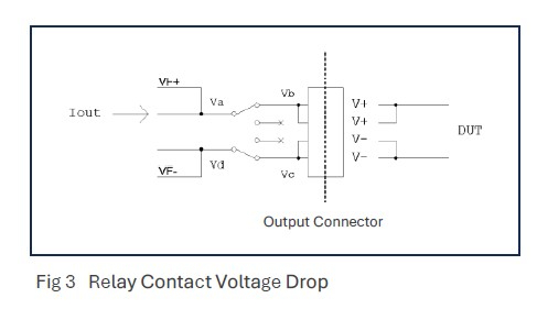
Channel voltage feedback is taken from the left side of the relay (VF+/VF−), while the right side of the relay is the connector output.
A small voltage drop may exist between the relay feedback side and the connector output side on both V+ and V− paths, represented by the voltage difference between Va/Vb and Vc/Vd.
The magnitude of this voltage drop is proportional to the output current.
Multi-Channel Sequential Output
Allows multiple channels to be configured together with programmable interval timing, controlling the output sequence of each channel for cell-stack simulation and high-cell-count BMS validation.
Multi-Channel Immediate Output
Allows multiple channels to be configured together and output at the same time for cell-stack simulation and high-cell-count BMS validation.
Slope Control
Controls voltage transition through programmable dv and dt settings, allowing cell-voltage variation during charge/discharge simulation. Supported range: dv = 0.001 V ~ 5 V, dt = 1 ms ~ 1000 ms.
Multi-Unit Series Configuration
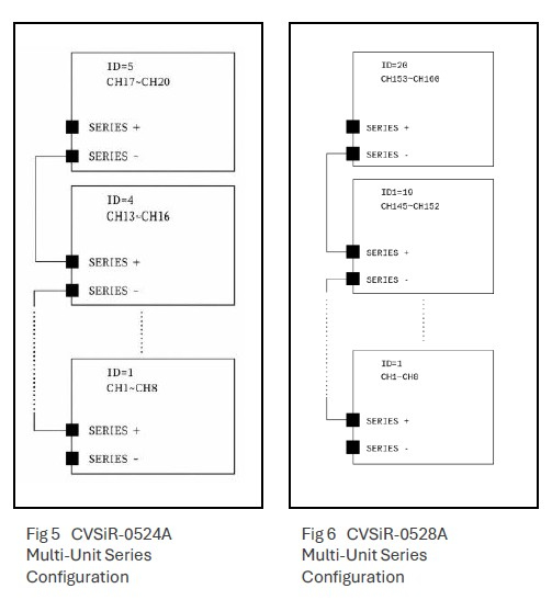
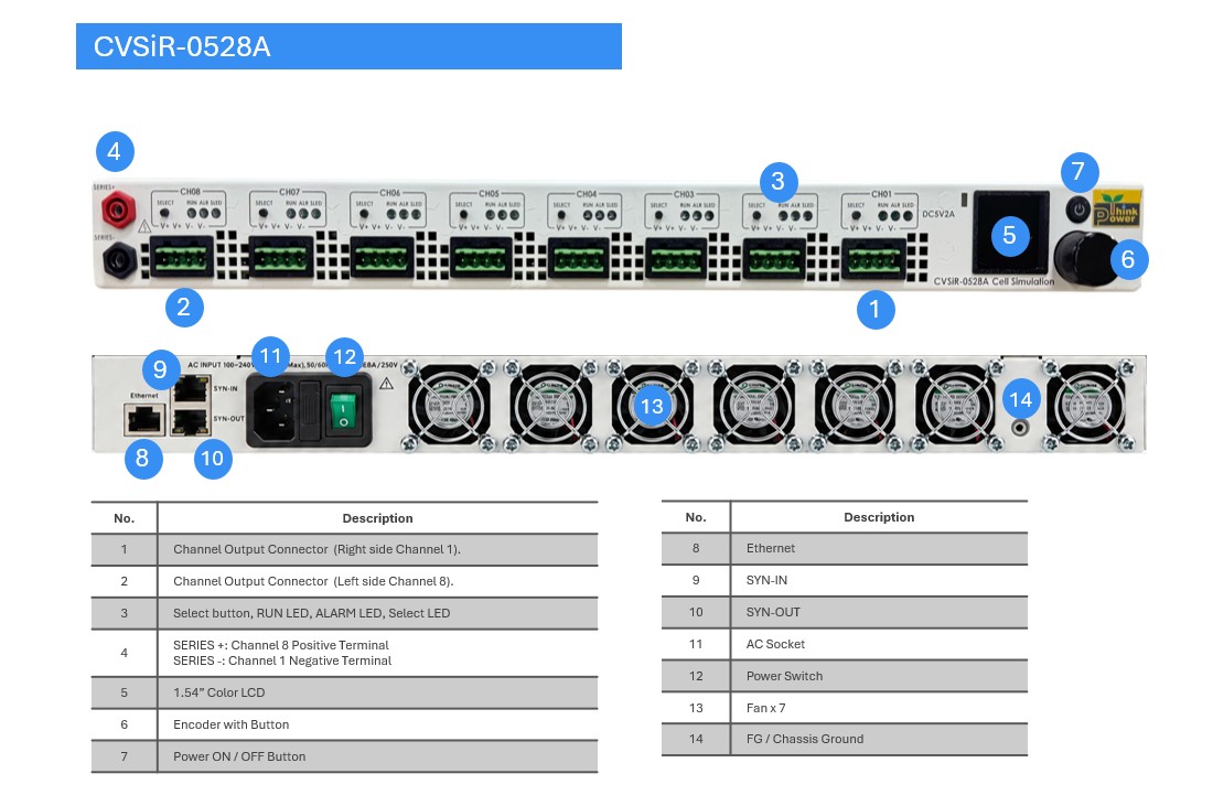
Multiple standalone units can be connected in series through the SERIES+ and SERIES− terminals to expand the available channels.
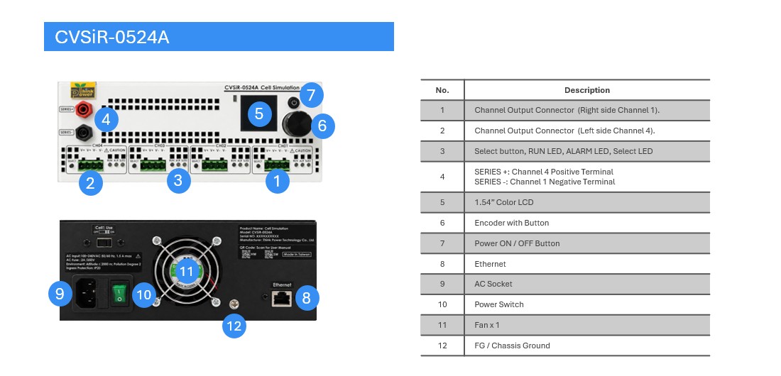
CVSiR-0524Acan be expanded up to CH1–CH20.
CVSiR-0528Acan be expanded up to CH1–CH160.
For CVSiR-0524A :
SERIES+is shorted to CH4 V+.SERIES−is shorted to CH1 V−.
For CVSiR-0528A :
SERIES+is shorted to CH8 V+.
SERIES−is shorted to CH1 V−.
SERIES+ / SERIES−can be regarded as the total positive and total negative terminals after the channels of each standalone unit are connected in series.
Synchronized Output
Supports synchronized output for single-unit or multi-unit operation, with CH1~CH160 output synchronization time of less than 10 ms.
Multi-Unit Sync
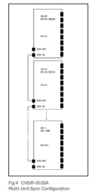
Supports synchronized operation across multiple CVSiR units through SYN-IN and SYN-OUT hardware interfaces. This function is suitable for expandable cell-stack simulation systems.
The unit containing CH1 is automatically defined as the master unit; all other units are automatically defined as slave units.
Multi-Unit Sync is supported by CVSiR-0528A only.
Protection Functions
Includes over-voltage, over-current, over-temperature, and resettable fuse protection.
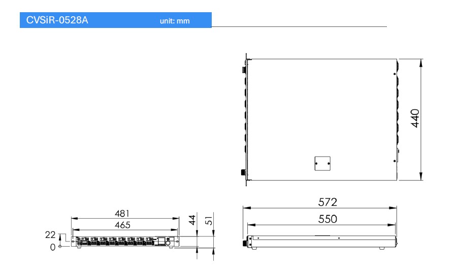
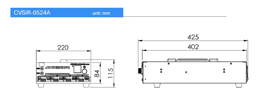
Mechanical
Human-Machine Interface
Local status display and quick operation for engineering validation
CVSiR provides a simple front-panel interface for local status checking, equipment informationdisplay, and quick operation during BMS validation.The color LCD, status indicators, encoder button, and buzzer allow engineers to identify system statuswithout relying solely on PC software.
One-year warranty provided.
新科電力科技股份有限公司
Think Power Technology Co., Ltd.
新北市五股區五權三路25號2樓
2F., No. 25, Wuquan 3rd Rd., Wugu Dist., New Taipei City, Taiwan
TEL:+886-2-22902095FAX:+886-2-22900586
Email:sales@think-power.com.tw
www.think-power.com.tw Specifications are subject to change without notice.2026-05-23